
TECHNICAL AND SAFETY INFORMATION
Glass Transport Systems: Technical & Safety
We pride ourselves on the quality and strength of our glass transport systems. We are confident we have the best value, highest quality glass frails on the market. Call us now for services in Bilston and across the UK.
Technical Specification
As well as the 3 year warranty offered on all glass transport systems from Top Fleet, there are many key areas that set us aside from other manufacturers in the industry.
Unique Aluminium Profile
Our glass racking products are constructed from a mix of 6063T6 and 6082T6 aluminium. T6 – Solution heat treated and artificially aged
aluminium alloy 6063/82 is a medium strength alloy with excellent corrosion resistance. It has the highest strength of the 6000 series alloys. The addition of a large amount of manganese controls the grain structure which in turn results in a stronger alloy.
6063/82 is typically used in:
- Highly stressed applications
- Trusses
- Bridges
- Cranes
- Transport applications
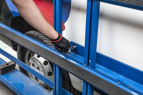
Rack Protector System
The rack protector is a sophisticated moulded block which is strong enough to secure the safety marker boards for the pole system, yet supple enough to absorb a percentage of the impact in the event of a collision. The rack protector also encompasses a wraparound reflector for high visibility from the front, back and side of the vehicle.
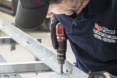
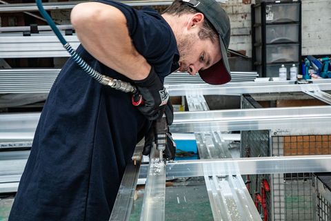
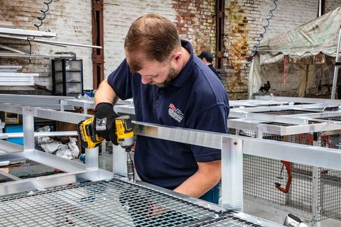
No Welding
Welds are much more susceptible to fatigue than mechanical fasteners. When aluminium cracks it usually begins at the weld. This is why we use Huck Magna-Grip® Lock Bolts for maximum strength and integrity.
Vibration proof
– absolutely will not loosen due to stresses produced by highway driving.
Flexibility
– lock bolts provide a secure bond with less rigidity to prevent cracking at joints.
Consistency
– the clamping force of each fastener is guaranteed to be uniform throughout construction.
Doesn’t compromise aluminium’s strength
– lock bolts possess high shear and tensile strength but won’t weaken the metal surrounding them.
Independent Safety Testing by CERAM
Test Report No. SW232/05
Watch our Glazing Vans in Action...
"Good quality product and fast turnaround"
Andrew - Andrew Milward Joinery
